

You're now following
Error following user.
This user does not allow users to follow them.
You are already following this user.
Your membership plan only allows 0 follows. Upgrade here.
Successfully unfollowed
Error unfollowing user.
You have successfully recommended
Error recommending user.
Something went wrong. Please refresh the page and try again.
Email successfully verified.

indore, india
It's currently 8:04 PM here
Joined January 1, 2020
8 Recommendations
Abbas J.
@SMBelectronics
6.0
6.0
94%
94%
indore, india
89%
Jobs Completed
84%
On Budget
81%
On Time
9%
Repeat Hire Rate
Electronics Engineer | Hardware & PCB Expert
Contact Abbas J. about your job
Log in to discuss any details over chat.
Portfolio
Portfolio


2.5 Gbps SerDes design using TLK2501

2.5 Gbps SerDes design using TLK2501


65W LED driver circuit

65W LED driver circuit

65W LED driver circuit

65W LED driver circuit

65W LED driver circuit

65W LED driver circuit

65W LED driver circuit


Glucometer

Glucometer

Glucometer
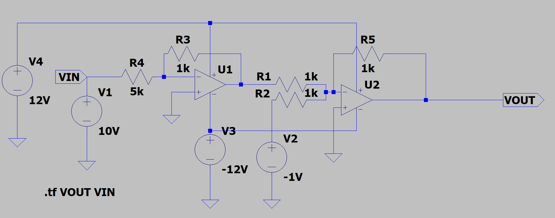

0-10V to 1-3V signal converter

0-10V to 1-3V signal converter

0-10V to 1-3V signal converter


PCB routing for BLE SoC


Ace-box data logger

Ace-box data logger

Ace-box data logger
2.5 Gbps SerDes design using TLK2501
2.5 Gbps SerDes design using TLK2501
65W LED driver circuit
65W LED driver circuit
65W LED driver circuit
65W LED driver circuit
65W LED driver circuit
65W LED driver circuit
65W LED driver circuit
Glucometer
Glucometer
Glucometer
0-10V to 1-3V signal converter
0-10V to 1-3V signal converter
0-10V to 1-3V signal converter
PCB routing for BLE SoC
Ace-box data logger
Ace-box data logger
Ace-box data logger
Reviews
Changes saved
Showing 1 - 5 out of 50+ reviews
$300.00 USD
Electronics
Electrical Engineering
PCB Layout
Product Design
Circuit Design

•
₹12,500.00 INR
Electronics
Microcontroller
PCB Layout
Arduino
Circuit Design
A
•
₹5,000.00 INR
Electronics
Microcontroller
Electrical Engineering
PCB Layout
Circuit Design
M
•
$500.00 USD
Electronics
Microcontroller
Electrical Engineering
PCB Layout
Circuit Design
L

•
Price undisclosed
Electronics
Electrical Engineering
PCB Layout
P

•
Experience
Electronic Engineer
Aug 2018 - Jan 2020 (1 year, 5 months)
At 3d prototyperz, I worked as Electronics Engineer and was responsible for designing developing and programming electronics systems for 3d printers and other machineries
Education
Bachelors of Engineering
(4 years)
Contact Abbas J. about your job
Log in to discuss any details over chat.
Verifications
Certifications
Top Skills
Browse Similar Freelancers
Browse Similar Showcases
Invite sent successfully!
Thanks! We’ve emailed you a link to claim your free credit.
Something went wrong while sending your email. Please try again.
Copy to clipboard failed, please try again after adjusting your permissions.
Copied to clipboard.
Loading preview
Permission granted for Geolocation.
Your login session has expired and you have been logged out. Please log in again.